Premier Industries, Inc.
Air Cooled Tube Bundle/Fin-Fan Typical Heat Exchanger
GENERAL: Any "air cooled" heat exchanger is designed to operate at maximum efficiency when the ambient air temperature is moderate, usually about 85(F) degrees. When the ambient air temperature rises above the maximum design point, the efficiency of the heat exchanger decreases. In fact the amount of decrease is usually inversely proportional to temperature rise.
The typical Tube Bundle or Fin-Fan type Heat Exchanger processes hot liquids or gas. The flow rate of the product through the tubes is greatly affected by ambient intake air temperature rise. Increased processing time (slower flow rate) can adversely affect other equipment in the production flow even further impacting product cost.
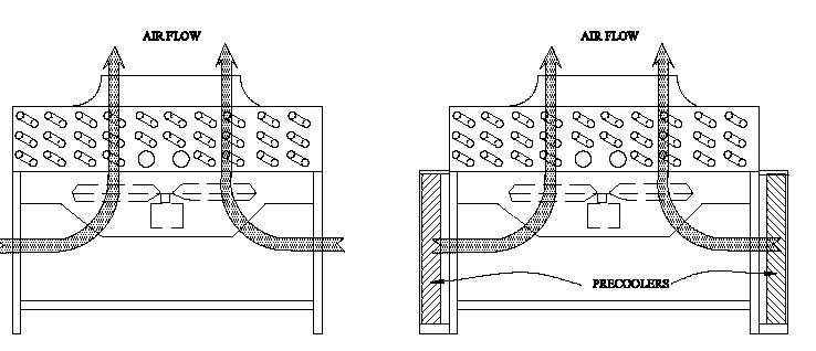
The simple solution to maintain maximum efficiency of the air cooled heat exchanger is to stabilize the temperature of the intake air at the equipment's design point. This can be done by adding evaporative Pre-Coolers.

The above illustration depicts a typical application of Pre-Coolers. This is a cross section drawing showing only the two sides of the heat exchanger.
Every installation of Pre-Coolers must be
properly sized and designed for the application. Some (but not all)
of the important requirements of a good design are:
1. All of the intake air must flow through the cooling
media in the Pre-Cooler.
2. Air velocity must not exceed 600 feet per minute.
500 feet per minute is preferred as a trade-off between efficiency and cost.
Velocity is determined by dividing the air flow volume (cubic feet per minute)
by the open face area (square feet). I.E. 50,000 CFM divided by 100 Square
feet (open face area of the cooling media) = 500 feet per minute velocity.
3. Media thickness determines the saturation (cooling)
efficiency of the Pre-Cooler. Static pressure drop across the media is a very
important consideration. The Heat Exchanger fans have limited static
pressure capability.
4. The table below defines percent efficiency and
pressure drop of different thicknesses of cooling media.
5. Access to the interior of the Heat-Exchanger must be
provided. This is usually accomplished by one or more walk through doors.
6. Consideration for piping and obstructions to the
Pre-Coolers attachment to the unit must be made.
7. Electrical controls and pumps must be explosion
proof when required. This is necessary in most Petroleum or Chemical
processing operations.
8. Pre-Cooler housing should be constructed using
Stainless Steel. Louver Panels are usually aluminum with birdscreen
attached.
9. There are many accessory items available for the
Pre-Coolers. Some important ones are low water protection for the pump,
Magnehelic gauges to indicate change in pressure drop across the media and
freeze protection.
Cooling Media Performance Characteristics
| Face Velocity | Percent Media Efficiency at Media Depth: | Static Pressure Drop at Media Depth: | ||||||||||
| 4" | 6" | 8" | 12" | 16" | 24" | 4" | 6" | 8" | 12" | 16" | 24" | |
| 200 FPM | 71% | 86% | 91% | 96% | 99% | 99% | 0.02" | 0.03" | 0.04" | 0.06" | 0.08" | 0.09" |
| 300 FPM | 67% | 81% | 88% | 94% | 98% | 99% | 0.03" | 0.05" | 0.07" | 0.10" | 0.13" | 0.19" |
| 400 FPM | 62% | 77% | 84% | 92% | 96% | 99% | 0.05" | 0.09" | 0.11" | 0.18" | 0.25" | 0.31" |
| 500 FPM | 59% | 72% | 82% | 89% | 94% | 99% | 0.09" | 0.12" | 0.17" | 0.26" | 0.36" | 0.50" |
| 600 FPM | 57% | 70% | 80% | 88% | 92% | 99% | 0.12" | 0.18" | 0.22" | 0.36" | ||
This table is based on data published by Glacier-Cor and Kuul Pad Cooling media manufacturers. The data are based on clean media and proper water flow rate to effect preferred saturation of the media. Water quality is also based on conditions similar to City water supply with low TDS (total dissolved solids) level.